ORNL Cluster v3.1
ORNL Cluster Help (v3.1)

by Jon Tischler
- Connecting to remote server
- The main dialog.
- Starting a job.
- Setting the reconstruction parameters.
- Set files for 2D data
- Setting the peak search parameters.
- Setting the indexing parameters.
- View the queue on server
- Starting and stopping the remote server.
Connect to the Server
The first thing that you will need to do is to connect to the server, otherwise
you are just talking to yourself. So go to the 'Server' menu and select one of
the listed servers. You will probably want hpcs34, but if you are running the
server on your own computer, then you can choose localhost.
Note, you can quit this program at any time and restart & reconnect to the server
without affecting any jobs executing on the server in any way.
What is the server doing now?
At the top of the main dialog, the status of the server will be shown.
Red means no connection,
green means the server is idle, and
blue means that the
server is busy.
If the server is running (blue), then you can see
what the server is doing by selecting "Server → View Queue on Server" or push the
"View Queue" button. This will put up a window showing the server status. If
the server is not processing any data, then this menu item and button are disabled.
Other server menu items: "Server → Disconnect from Server" allows you to
disconnect from the server you are currenly connected to. It will only be enabled
when you are connected.
The menu item, "Server → Start Server on localhost" allows you to start
a server on your local computer (useful for off-line computation and testing).
The associated menu item "Server → Kill Server on localhost" kills the local server
that you started. NOTE, the local server does not quit running when
you quit THIS program. If you start a local server, it will continue to
run on your computer until you reboot your machine, kill it manually using
the "screen -r" command, or select the "Server → Kill Server on localhost"
menu item.
Setting Up a Job
To actually do some computations you have to provide all sorts of information to
let the server know what to do and how to do it. There are various ways to
provide this information.
The simplest way to set all input parameters is to open a local xml file (on your
computer) that has all of the input parameters already in it. To do this go to the menu
"File → Open", and select the desired xml file. Later on I will explain how to
create such a file.
Another easy way to get the required input information is to ask the server. If
you go to the menu item "Server → Get All Values from Server", or push the
"Get←Server" button, all of the input parameters
currently set in the server will be downloaded into this client program.
The normal way to provide the required information is by fillng out all of the dialogs.
Since this is more time consuming, I suggest first using one of the two previous methods
(file or download) to preset everything to reasonable values.
Then proceed through all of the dialogs until all parameters are set.
When all values are entered and set to your satisfaction and Validated, you can save these
settings to an xml file by the menu item "File" → "Save As...". This saved
file can then be read in at a later date to either re-do the same calculation or
one only slightly different.
Main Dialog
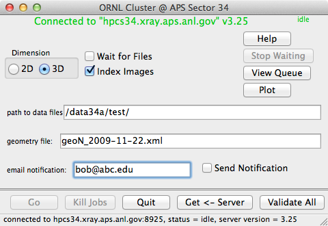
- 2D/3D button
- 3D means there is a wire scan and so a reconstruction should be done.
If no reconstruction (no wire scan), then choose 2D.
- Wait for files
- This causes the analysis to analyze the data as it is taken. This
is useful when you start the analysis before the measurement is
finished. If the data have already been taken, do not check this box. For
example, do not check the box if you are re-analyzing old data.
- Index Images
- Causes the images (either reconstructed or not) to be indexed. This
needs to be checked if you want to know the orientation of a Laue pattern.
If you do not have Laue pictures that can be oriented, then do not check the box.
Usually you will check this box for white images. For monochormatic (or energy
scans) you should probably not check this box.
- path to data files
- This is a prefix path that will be prepended to all data (both input and output),
geometry, and xtal files. Again it is relative to the cluster nodes, not
the computer that you are using. This path is not required, but it will make things much
easier for you.
- geometry file:
- This locates the geometry file needed for reconstruction and indexing.
The full path to the geometry file from the server's point of view is "path to
data files"/"geometry file".
- email notification:
- When the computation finishes, the server will send an email to this address
if the "Send Email" checkbox is checked. If you do not want such a notification
sent, then either clear the email address, or uncheck the box. In the example
above no email will be sent to bob. Note, if you want the notification sent
to your cell phone as a text message, use something like [email protected]
(assuming that your carrier is AT&T, for other carriers
see the List of SMS gateways on wikipedia).
buttons:
- Help
- Brings up a view of this help.
- Go
- Start analysis running on the server using the supplied parameters. If
buttong is disabled (grayed out), then you need to first validate the parameters
(see Validate All below).
- Kill Jobs
- Kills all currenly executing and pending jobs on the server. Use this when
you just want to stop everyhthing. Using this will often leave some of the intermediate
text files lyng around in raw or reconstructed image folders. There is no way
to automatically delete these files after pushing "Kill Jobs"
- Quit
- Quits this program.
- Get←Server
- Get all of the input parameters from the server.
This sets up everything just as it is in the server, very useful when you
re-connect to the server and want to set everything just as it was when you
last quit. This is equivalent to the menu item "Server → Get All
Values from Server".
- Validate All
- Send ALL values from this program (not just the ones on this panel) to
the server and has the server check them for validity. This includes checking
that all required paths and (most) of the files exist at the server. Use this
just before the 'Go' button. You need to do this before pushing the
Go button or doing a "Save As..." from the menu.
- Stop Waiting
- This button is only available when "Wait for Files" is checked. Initially
disabled, after a job is started, this button allows the user to tell the server
to stop waiting for more input images. It is particualarly useful when you start
a job with the range "1-inf". When the scan finishes, push the "Stop Waiting" button.
- View Queue
- Initially disabled, when the server is running jobs, this button will open the
queue activity window. It is equivalent to the
Server → View Queue on Server
menu item.
- Plot
- Show a plot of the total intensity vs depth for the last reconstruction. This is
meant as a means of monitoring the currently running reconstruction. It is not very
useful for viewing data.
Server → Plot Last Reconstruction on Server
menu item.
- Top
Other Dialogs:
There are three other dialogs that need to be accessed before starting a calculation.
They are accessed from the "Set" menu.
- Set → Reconstruct...
- Set → Set 2D Files...
- Set → Peak Search...
- Set → Indexing...
- Server → View Queue on Server
- Top
Set → Reconstruct...
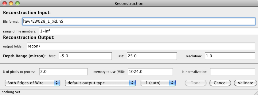
This is used to set the parameters needed for doing a reconstruction (3D) data.
For 2D data this panel is not needed.
- file format:
- path to the raw images. This is relative to the "path to data files"
from the main panel. For multiple detectors, separate file formats by a comma,
e.g. "raw/Si_Orange_%d.h5, raw/Si_Yellow_%d.h5, raw/Si_Purple_%d.h5" The "%d"
format specifier is iterated over all items in the range.
- range of file numbers:
- An integer range that designates the file numbers to reconst. Valid forms are:
5
1-10
1,5,9-50
1,2,70-inf
- output folder:
- Relative path to the folder that receives the reconstructed images.
For multiple detectors, separate the folders e.g. "recon/, recon/, recon/"
or "reconO/, reconY/, reconP/"; putting all files in the same folder is preferred.
- Depth Range, first:
- depth (µm) of the first reconstructed image.
- last:
- depth (µm) of the last reconstructed image.
- resolution:
- distance or depth (µm) between each reconstructed image.
- % of pixels to process:
- Most fo the pixels in each Laue picture contain no
information, so reconstructing them provides no benefit. For lots of big images,
reconstructing all of the pixels in each image will take a long time, this
parameter will help speed the process by ignoring the unimportant pixels.
The procedure used to decide which pixels are important is as follows:
the first image in each wire scan is examined, and the most intense 10% (if
this value is set to 10) of the pixels are the only ones that are
reconstructed. This parameter is useful for big Laue images. For energy
wire scans which usually use only a small region of the detector, use 100%.
- memory to use:
- Amount of memory (in MiB = Megabytes) to use for the reconstruction. Good
values are 4096 (equivalend to 4 Gigabyte) for the cluster and 2048 on the Mac.
- Io normaliztion:
- Can be used to normalize the data to a PV that was stored in each
image. Often left blank.
- Wire Edge
- Tells the reconstruction which edge(s) of the wire to use. We usually
use Both Edges of Wire. This works best unless your sample has
good crystalline grains larger than the wire diameter. Then you should use
Leading Edge of Wire. The Trailing Edge is only for
completeness, and is seldom used.
- output type
- Determines the number type that is used for saving the reconstructed
images. Usually use default output type. However, it is possible
to save disk space by choosing 2 byte signed int (short). This
only works well when the reconstruction does not produce any really strong peaks.
If you do not know what you are doing, use the default.
- detector to use
- You can specify the detector that is used. Generally this is a bad idea,
the analysis programs should figure this out for themselves based on information
in each image. So just choose -1 (auto). However if something is wrong, you
can force a particular detector geometry to be used by specifying the detector
here. Do not mess with this if you are not sure, just use auto.
buttons:
- Done
- Dismisses this dialog, all values entered in this dialog will be
saved for use. If this button is disabled, try the Validate button.
- Cancel
- Cancel this dialog, do NOT use the values entered here, they are discarded.
This is equivalent to just closing the window.
- Validate
- Does a simple check on the entered values. This is only a local check,
the server is not involved. You have to do a Validate to activate
the Done button.
- Top
Set → Set 2D Files...
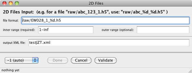
This is used to set the parameters needed for indexing many image files, probably
a 2D scan.
- file format:
- path to the raw images. This is relative to the "path to data files"
from the main panel. The %d is replaced by each integer in the range.
This can have one or two format items, e.g. EW_%d_%d.h5, When there are two format specifiers,
then it is necessary to also specify two ranges (inner and outer). The outer range goes with
the first "%d", and inner with the last "%d". When the format has only one %d, then leave the
out range blank.
- inner range (required):
- An integer range that designates the file numbers to process. If there are
two format specifiers in the file format, then this is the last one. If there
is one format specifier (i.e. %d) then this is the range used.
- outer range (optional):
- An integer range that designates the file numbers to process. This is only
used if there are two format specifiers in the file format, then this loops over
the first "%d". If there is only one format specifier then this field should
be blank.
- output xml file:
- This is the path to the output xml file (contains result of indexing).
The full path of this file from the server's point of view will
be "path to data files"/"xml file for output". For 3D data this file name is automatically
generated, but for 2D data you need to supply it.
- detector to use
- You can specify the detector that is used. Generally this is a bad idea,
the analysis programs should figure this out for themselves based on information
in each image. So just choose -1 (auto). However if something is wrong, you
can force a particular detector geometry to be used by specifying the detector
here. Do not mess with this if you are not sure, just use auto.
buttons:
- Done
- Dismisses this dialog, all values entered in this dialog will be
saved for use. If this button is disabled, try the Validate button.
- Cancel
- Cancel this dialog, do NOT use the values entered here, they are discarded.
This is equivalent to just closing the window.
- Validate
- Does a simple check on the entered values. This is only a local check,
the server is not involved. You have to do a Validate to activate
the Done button.
- Top
Set → Peak Search...
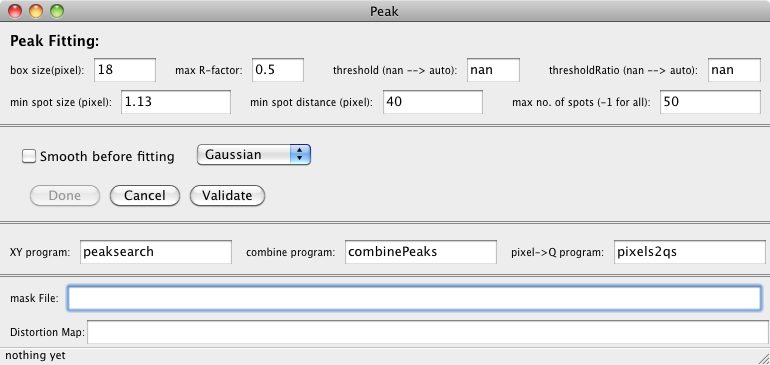
This controls the peak searching which is a preliminary to the indexing. It is
not used for energy scans (e.g. an energy wire scan).
- box size
- Gives a size used for finding and fitting a peak. Typical values are 5
for sharp peaks, and 18 for larger peaks.
- max R-factor
- Reject peaks whose fit has an R-factor greater than this value. Usually use 0.5.
- threshold
- The threshold used for peak searching. Usually just use nan, and let
the program choose one for itself.
- thresholdRatio
- This provides help to the program when auto setting the threshold for peak searching.
When the threshold is specified, this is ignored. You may also set this to nan,
and let the program choose one for itself.
- min spot size
- Reject spots with size smaller than this number. For larger spots use
1.1, for sharp peaks or for Gaussian shapes use smaller values such as 0.3.
- min spot distance
- Do not accept peaks that are within this distance from each other.
This keeps fitted peaks from being to close together.
- max number of spots
- Used to limit the number of spots found and fitted. Use -1 to accept
all. Hoever, big nubmers (>50) can sometimes cause problems with the indexing.
- Smooth before fitting, Check Box
- This does a smooth operation on the image before fitting, not usually
needed. This only works when using peaksearchBox.
- Gaussian/Lorentzian
- Function to be used for fitting the peaks. The Gaussian definitely
works better for sharp peaks, and is usually a better choice.
buttons:
- Done
- Dismisses this dialog, all values entered in this dialog will be
saved for use. If this button is disabled, try the Validate button.
- Cancel
- Cancel this dialog, do NOT use the values entered here, they are discarded.
This is equivalent to just closing the window.
- Validate
- Does a simple check on the entered values. This is only a local check,
the server is not involved. You have to do a Validate to activate
the Done button.
programs:
- XY program:
- Name of program (relative to the "binary path") to be used for finding
peaks on images. Usually use peaksearch, sometimes
peaksearchBox works better, but rarely. If you are using a special
peak search routine, here is where you specify it.
- piexl → Q program:
- Name of program (relative to the "binary path") that takes ouput from
XY program and the geometry file and produces the list of Q hats
used by indexing program. Usually use pixels2qs.
- combine program:
- Name of program (relative to the "binary path") that takes Qhat ouput
from multiple detectors and combines them into one file that is used by the
indexing routine. For single detector data this program is not neede.
Usually use combinePeaks.
files:
- mask File:
- Name of an optional file with a mask to for the peak fitting. This name is
also relative to the "path to data files". The mask file is an hdf5 file that
can be made with Igor. Using a mask allows you to exclude substrate peaks from the
peak searching.
- Distortion Map:
- Name of an optional file containing a distortion map to correct pixel positions.
This is only used with the Roper detector. Leave this blank for other detectors.
- Top
Set → Index...
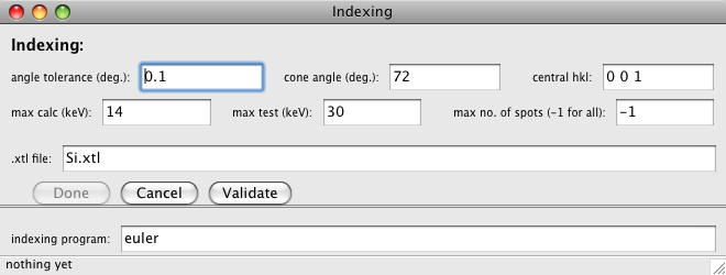
This dialog provides the parameters used by the indexing routine. The indexing
routine uses the measured Qhats from the peak searching step to determine the
orientation of the crystallite(s). The indexing routine will give a list of
orientations if multiple Laue patterns are present. The output list should
be ordered so that the best patern is first.
- angle tolerance
- The indexing program compares all pairs of measured Qhats to all pairs
of possible Qhats. But only considers those pairs which have the same angular
separation to within this tolerance. It also uses this angle in the final
allocation of measured Qhats to a derived orientation.
- cone angle
- central hkl
- max calc (keV)
- These three parameters determine the set of possible hkl that
are used when indexing a pattern. The hkl that are considered when
indexing are all hkl that are within cone angle
of the central hkl, and whose energy will be below
max calc. Note, max calc only limits the
hkl that are used to find an orientation, the indexing process
contains a second pass where spots with higher energies may be included
in a pattern.
- max test (keV)
- Energy used when determining which measured spots belong to an orientation.
Once an orientation has been determined (using cone angle,
central hkl, and max calc) another list of
hkl's is generated this time accepting energies out to max test.
It is this new list that is used to identify which measured spots belong to this
orientation. Note, this process is done for each orientation found in a Laue pattern.
- max no. of spots
- Limits the number of spots used to index a pattern. The indexing program
will only use the first N spots from the peak search program.
- .xtl file
- File with extension .xtl containing the definition of the
crystal that we are trying to index. The actual file is relative to the
"path to data files" in the main dialog. The current version of euler also understands
crystal description files with the .xml extension.
buttons:
- Done
- Dismisses this dialog, all values entered in this dialog will be
saved for use. If this button is disabled, try the Validate button.
- Cancel
- Cancel this dialog, do NOT use the values entered here, they are discarded.
This is equivalent to just closing the window.
programs:
- indexing program:
- Name of program (relative to "path to binaries") that does the indexing.
Usually euler. Unless you are using some special program
(which does not yet exist), use euler.
- Top
Server → View Queue on Server
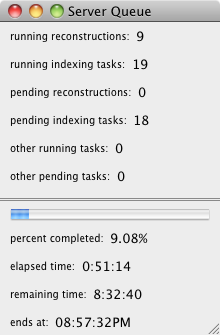
This menu item is only available after a calculation has been started and is
running; it has no input parametes. It provides information about how many jobs are
currently running on nodes in the cluster, and about how many jobs are queued up
for the cluster. It also gives information about the progress of the current calculation.
- running reconstructions:
- The number of reconstructions that are currenly executing on cluster
nodes.
- running indexing tasks:
- The number of peaksearch/indexing tasks that are currenly executing on cluster
nodes.
- running compress tasks:
- The number of compress or unCompress tasks that are currenly executing on cluster
nodes.
- pending reconstructions:
- The number of reconstructions that are waiting in the queue for a free
compute node.
- pending indexing tasks:
- The number of peaksearch/indexing tasks that are waiting in the queue
for a free compute node.
- pending compress tasks:
- The number of compress or unCompress tasks that are waiting in the queue
for a free compute node.
- other running tasks:
- The number of tasks running on the cluster that were NOT started by
this application. These tasks were put on the cluster by something/someone
else that we don't know about. In general this should be zero.
- other pending tasks:
- The number of tasks that are waiting in the queue for a free compute
node that were NOT started by this application. These tasks were put on the
cluster queue by something/someone else that we don't know about. In general
this should be zero.
- A progress bar

- Shows progress for this submitted calculation. When the blue reaches
the right side it should finish.
- percent completed:
- Fraction of this calculation that has been completed. This is also the
fractional length of the blue in the progress bar. If the range contains an 'inf',
then this number is likely to be invalid.
- elapsed time:
- Amount of time since this calculation was started.
- remaining time:
- Predicted amount of time needed for this calculation to finish.
- ends at:
- Time of day when this calculation is predicted to finish.
- Top
Starting (and Stopping) the Remote Server
This is typically an Administrator function, so you should
not generally need to know about this.
These following commands are typical of those used to start (and stop) the remote server.
These commands can also be used on your local machine to start/stop a localhost server,
but the menu items are easier to use for localhost. Note, for a server on your local machine,
the -q and -r switches are ignored, since your local machine has no queues, only the cluster has queues.
First open a terminal window and log into the machine that you want to
run the server on (usually hpcs34.xray.aps.anl.gov), and navigate to
the folder containing the server python scripts.
Then it is usualy best (but not required) to start the server in a detachable
window, so type the command:
$screen
This starts a new screen session which can be detached. Then actually
start the server by executing the Python script, type (this start server using the xmd.q queue):
$./server.py -q xmd
The xmd.q queue is the default, so an equivalent command is:
$./server.py
To start the server using either the xmdfast.q or extra.q queues, use:
$./server.py -q fast
$./server.py -q extra
And finally, to start the server using the gpu-all.q queue for the reconstructions and xmd.q for all other tasks:
$./server.py -q xmd -r gpu
The server should now be running. The terminal should tell you that output
from the server is being redirected to a file named serverLog.txt in
the current folder. You can look at this log file at any time from any terminal.
You can now detach from this screen (and log out) without stopping the server
To detach from this screen, type in:
$[Ctrl+A] [D]
that is just two characters, first the "Ctrl+A", and then a
"D". Now the server is running in a detached screen and you can log
out or do whatever you want without stopping the server.
To re-attach to the server process (probably to kill it), log into the
same machine that you started it on and type:
$screen -r
This will re-attach you to your previously detached screen and allow you to do things
such as killing the server. To kill the server, just type one character:
Ctrl+C
If you want to run the server without a separate screen session, simply log
in and type one of the above commands such as:
$./server.py
This will work fine. However, if you log out or kill the terminal window, the
server will be killed, which is probably not what you want. By using the
screen command you can detach and log off the computer while the
server continues to run, which is what you generally want for normal operations.
It should also be possible to run the server with a nohup command,
but I have not yet tried that, and don't see any advantage to using it.
Top